
Author: Site Editor Publish Time: 2026-11-05 Origin: Site
As modern electronic devices grow increasingly compact and relentlessly powerful, engineers face a universal adversary. That adversary is excess heat. When microprocessors, graphics cards, and power modules operate at peak capacity, the thermal energy they generate can quickly lead to catastrophic hardware failure. The core of this issue often lies at the microscopic level. To the naked eye, the metal surfaces of a component and its cooling hardware appear perfectly smooth. In reality, they are riddled with microscopic imperfections. These tiny valleys create heat-trapping air pockets. Air is a terrible conductor of heat. Therefore, these invisible voids act as thermal insulators, causing devices to rapidly overheat.
Enter the silicone gap filler. This is a highly specialized thermal management solution engineered to eradicate this exact problem. By physically filling these microscopic voids and macroscopic spaces, these materials create a seamless solid-state bridge. This physical connection allows heat to escape efficiently. This comprehensive guide breaks down exactly how these materials work. We will explore the critical specifications you must evaluate and how to select the optimal setup for your specific hardware architecture from a frontline engineering perspective.
Silicone gap fillers effectively displace insulating air pockets located between heat-generating electronic components and cooling hardware, establishing a highly efficient thermal bridge.
The overall cooling effectiveness of an interface material is heavily determined by its thermal conductivity rating, standardly measured in Watts per meter-Kelvin.
Compression deflection serves as a critical safety metric. The material must remain soft enough to conform to uneven topographies under mounting pressure without cracking fragile silicon dies.
Implementing a proper thermal boundary is absolutely essential for maximizing the heat dissipation performance of any cooling block.
Choosing the optimal setup involves a careful, application-specific balance of material thickness, Shore OO hardness, and long-term structural stability.
A Gap Pad is a pre-formed, flexible, and thermally conductive solid material specifically engineered to transfer heat within modern electronic assemblies. Unlike liquid thermal pastes or rigid metal spreaders, these sheets offer a unique combination of structural integrity and mechanical compliance. They act as a reliable medium to bridge the physical space between a heat-generating component, such as a CPU or Voltage Regulator Module, and the cooling hardware designed to dissipate that heat.
To fully grasp their functionality, it is important to examine their material composition. The base structure consists of a soft, compliant silicone elastomer. Silicone is deliberately chosen for its exceptional temperature stability. It maintains its physical properties across extreme ranges, often from minus 40 to over 200 degrees Celsius, without degrading, drying out, or melting. However, raw silicone is naturally a thermal insulator. To transform it into a heat-transferring powerhouse, manufacturers load the elastomer matrix with highly conductive ceramic particles. Common fillers include aluminum oxide, zinc oxide, or boron nitride. When processed into a dense sheet, these tightly packed ceramic particles create microscopic pathways for kinetic energy to travel through.
Furthermore, beyond raw heat transfer, these materials possess several characteristics that make them indispensable on the assembly line. They feature a naturally tacky surface, which holds the material securely in place before the cooler is bolted down. Because they rely on ceramic rather than metallic fillers, standard sheets provide excellent electrical insulation. For instance, high-quality industrial pads often feature a dielectric breakdown voltage exceeding 4 kilovolts per millimeter. This prevents catastrophic short circuits if the material touches exposed pins or traces on a Printed Circuit Board. Finally, their solid-state nature allows them to be precisely die-cut into custom shapes, ensuring clean and repeatable installations without the mess of liquid compounds.
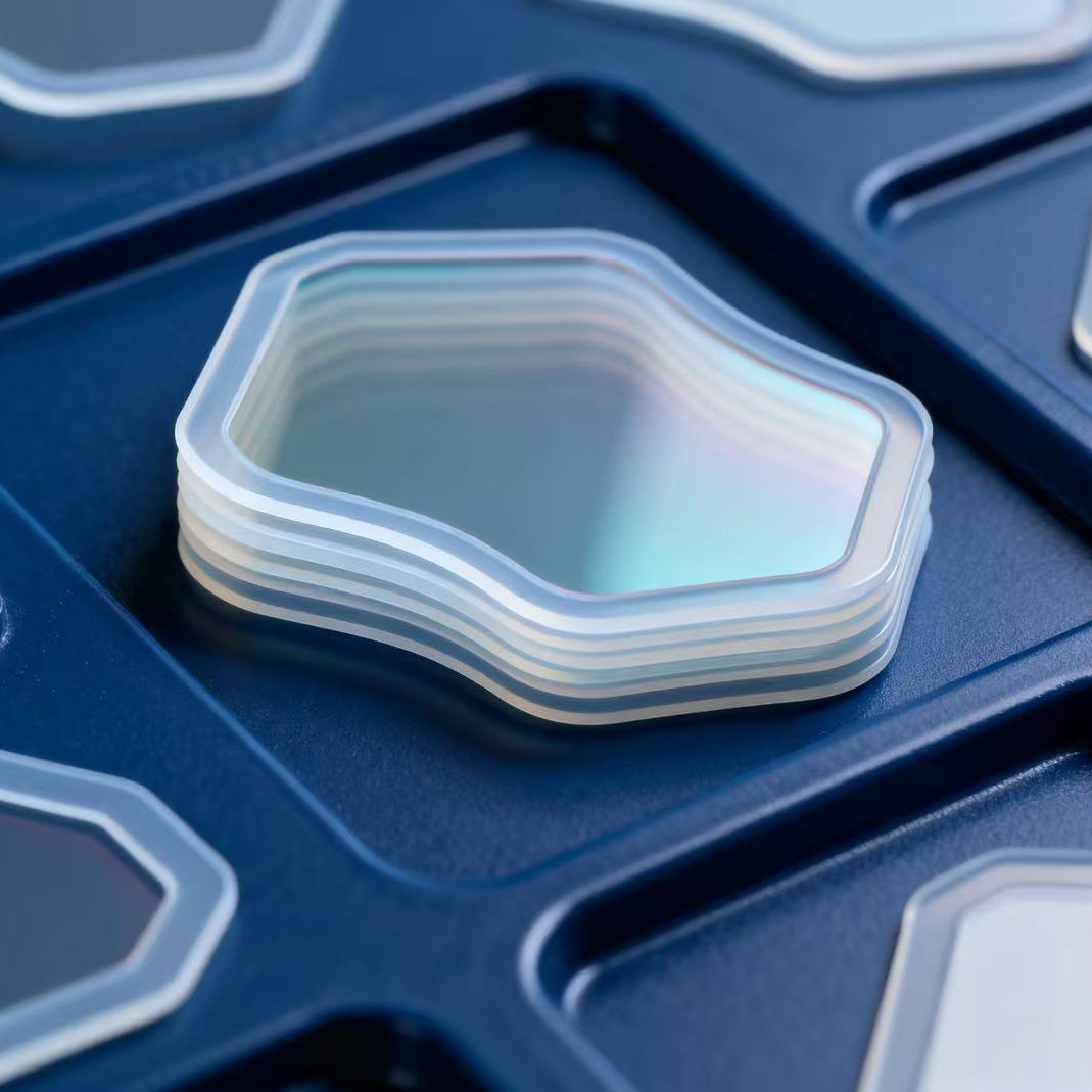
In the realm of thermodynamics, thermal resistance is the primary enemy of efficient cooling. When you place a rigid processor lid against a flat copper cooling block, only the microscopic peaks of the two metals make physical contact. The microscopic valleys do not touch, creating a network of tiny voids that immediately fill with ambient air. Given that air has a thermal conductivity of roughly 0.026 Watts per meter-Kelvin, it acts as a formidable thermal wall. If these air gaps remain unaddressed, the heat generated by the silicon cannot efficiently transfer to the cooler. This inevitably triggers thermal throttling and eventual shutdown.
Specifically, this is where the compliant nature of the material shines. When placed between the hot component and the cooling hardware under appropriate mounting pressure, the soft silicone matrix physically deforms. It flows gracefully into the microscopic valleys and surface irregularities of both surrounding metals. By completely displacing the insulating air pockets and replacing them with a thermally conductive solid, the overall thermal resistance of the assembly plummets. The junction transforms from a series of insulated bottlenecks into a continuous, high-speed thermal highway.
Once this physical bridge is established, the actual process of thermal conduction takes over. As the electronic component operates, it generates intense kinetic energy known as heat. This energy excites the ceramic filler particles suspended within the silicone matrix closest to the heat source. Because these particles are densely packed, the kinetic energy rapidly cascades from one particle to the next, traveling through the thickness of the material. The heat follows this path of least resistance until it reaches the cooler side. There, it is absorbed and eventually dissipated into the surrounding environment by the aluminum or copper fins.
As the technology landscape shifts, the demands placed on thermal management materials are evolving rapidly. Driven by the explosive growth in artificial intelligence processing, the rollout of densely packed 5G telecommunications equipment, and the high-voltage demands of electric vehicle battery packs, components are generating more heat in significantly smaller footprints. Industry analysts note a distinct market shift toward ultra-soft, highly compressible gap fillers with exceptional heat transfer capabilities.
Engineers are increasingly prioritizing materials that can accommodate the intricate, multi-level topographies of heavily populated circuit boards without exerting undue stress on miniaturized solder joints. In addition, the global push for sustainable, long-lasting electronics is making the structural stability of solid silicone elastomers more appealing than ever. Unlike traditional liquid pastes that degrade and require frequent maintenance, solid elastomers offer a set-and-forget reliability. This aligns perfectly with the extended warranty cycles of modern industrial and consumer technology.
Thermal Conductivity is the fundamental metric used to quantify a material's ability to conduct heat. In the context of thermal management, it is universally measured in Watts per meter-Kelvin, commonly abbreviated as W/mK. This value represents the amount of heat energy that can pass through a one-meter thickness of the material when the temperature difference between the two sides is one Kelvin. Simply put, a higher rating indicates a more aggressive heat transfer capability.
When evaluating these materials, understanding the practical application of different ratings is vital for making an informed engineering decision. Over-speccing can lead to unnecessary costs, while under-speccing can lead to catastrophic hardware failure.
Conductivity Range | W/mK Rating | Ideal Electronic Applications |
|---|---|---|
Low Range | 1.0 to 3.0 W/mK | Memory chips, LED lighting arrays, microcontrollers, and low-power consumer electronics. |
Mid Range | 3.0 to 8.0 W/mK | Standard desktop processors, graphics cards, motherboard power modules, and standard power supplies. |
High Range | 8.0 to 12.0+ W/mK | High-performance computing servers, electric vehicle battery management systems, and heavy-duty industrial power electronics. |
For procurement engineers and PC builders alike, the purchasing decision requires a nuanced approach. It is a common misconception that one should simply buy the product with the highest possible rating. However, to achieve extreme conductivity, manufacturers must pack massive amounts of ceramic filler into the silicone matrix. This heavy loading often makes the product significantly harder and less compressible, which can introduce dangerous mechanical stress to the circuit board. The most objective approach is to calculate the actual Thermal Design Power of your component. Then, select a rating that safely handles that specific heat output without sacrificing material softness.
While thermal conductivity dictates how fast heat moves, Compression Deflection dictates mechanical safety and long-term reliability. This engineering metric is defined as the amount of physical pressure, usually measured in psi or kilopascals, required to compress a material to a specific percentage of its original uncompressed thickness. For instance, a specification sheet might state that a product requires 20 psi to achieve a 30 percent deflection. This tells you exactly how much force the mounting hardware will exert on the delicate electronic components below when the assembly is tightened down.
Maintaining a delicate balance in compression is critical for the survival of your hardware. Imagine tightening a heavy copper cooler onto a bare-die graphics chip. If the material beneath is too rigid, meaning it exhibits high compression deflection, it will resist deformation. The mechanical stress from the screws transfers directly through the material and into the fragile silicon. This potentially causes a catastrophic crack or fractures the microscopic solder joints beneath the chip.
Conversely, if the material is excessively soft, it presents a different set of risks. Under sustained pressure and thermal cycling, an overly soft material might permanently deform or ooze out from the sides of the components. It may also suffer from compression set, failing to maintain consistent contact over the lifespan of the device.
High-quality thermal elastomers are engineered to hit a specific mechanical sweet spot. Manufacturers achieve this by utilizing a low-modulus silicone matrix that yields easily under minimal mounting pressure. In most electronic applications, compressing the material by 20 to 50 percent of its original thickness is considered ideal. This level of deflection ensures the material fully conforms to surface irregularities and absorbs the mechanical tolerances of the assembly, all without transferring dangerous stress to the circuitry.
The fundamental role of a Heat Sink is to drastically increase the surface area available for thermal dissipation. This allows energy to be transferred into the surrounding air via natural or forced convection. Yet, a massive and highly efficient aluminum fin array is entirely useless if the heat generated by the silicon cannot reach its base efficiently. The thermal bottleneck almost always occurs at the physical junction between the two components.
By acting as a compliant volumetric bridge, the elastomer ensures that the cooling hardware operates at its maximum designed capacity. One of the most significant architectural advantages of these solid sheets over liquid alternatives is their ability to handle varying component heights. In complex assemblies like laptop motherboards, a single flat cooling pipe often needs to cool a central processor alongside surrounding peripheral components, such as memory chips and power transistors.
Due to standard manufacturing tolerances, these adjacent components are rarely the exact same height. A solid and compressible material can be applied in varying thicknesses across these different chips. When the flat cooling block is mounted, the materials compress at different rates. This easily absorbs the height discrepancies. As a result, it connects an entire landscape of varying components to a single unified cooler without requiring highly complex CNC machining on the metal block itself.
When designing a thermal management system, choosing the correct Interface requires an objective assessment of your hardware physical architecture. Both solid sheets and pastes serve the same fundamental purpose, but their physical states dictate entirely different use cases.
Thermal paste, also known as thermal grease, is a semi-liquid suspension of conductive particles. It is the optimal choice for ultra-thin direct-contact applications where the physical distance between the heat source and the cooler is practically zero, often less than 0.05 millimeters. A classic example is mounting a CPU cooler directly onto the integrated heat spreader of a desktop processor. In these microscopic gaps, thermal paste excels because it spreads into an exceptionally thin bond line, offering the lowest possible thermal resistance. However, it is messy to apply and susceptible to the pump-out effect. This is where repeated thermal expansion and contraction eventually push the liquid out of the joint over time.
In contrast, a solid elastomer sheet is the superior choice in several distinct engineering scenarios. When the hardware design leaves a deliberate macroscopic space, ranging from 0.5 to over 5 millimeters, a liquid paste cannot physically span the void. A solid sheet acts as a volumetric filler. As previously noted, when a single flat cooler must connect with multiple chips of varying heights, the compressibility absorbs these tolerance differences safely. Because it is a cured solid, a silicone sheet does not suffer from pump-out. It remains structurally stable over years of continuous thermal cycling, making it ideal for maintenance-free devices.
If you are mounting a high-pressure cooler to a single perfectly flat processor with a non-existent gap, thermal paste provides the lowest resistance. Conversely, if your assembly features visible gaps, requires cooling multiple adjacent components with a single block, or demands long-term mechanical stability without the risk of degradation, a solid silicone sheet is the undisputed engineering solution.
Selecting the correct thermal management material is not a guessing game. It is an exercise in precision. Choosing a product that is too thin results in poor contact and overheating, while choosing one that is too thick can exert excessive mechanical stress on delicate solder joints.
The most crucial step is accurately measuring the physical space between your heat-generating component and your cooling block when the hardware is fully assembled. Engineers typically use tools like digital calipers or feeler gauges to measure this void. Once you have the precise measurement, you must account for mechanical tolerances. The industry standard rule of thumb is to purchase a product that is 10 to 20 percent thicker than your measured gap. For example, if your measured gap is 1.0 millimeter, you should select a thickness of 1.2 millimeters. This extra thickness guarantees that the material will undergo the necessary compression to fill all voids once the assembly is torqued down.
The softness of these materials is typically measured on the Shore OO scale. This rating directly correlates to how easily the material yields under pressure. An ultra-soft rating between 10 and 30 requires very little pressure to compress. This is ideal for fragile bare silicon dies or thin circuit boards that might bend under stress. A medium-hard rating between 40 and 60 is the industry sweet spot. It offers a perfect balance of conformability and structural integrity for standard computer hardware. Finally, a firm rating of 70 or higher requires significant mounting pressure. This is typically used in heavy-duty industrial applications or battery packs where the material also provides mechanical support.
While pure silicone provides excellent thermal transfer, highly compressible versions can tear easily if subjected to shear forces during installation. To combat this, manufacturers often embed a woven fiberglass mesh within the matrix. This fiberglass layer dramatically increases tensile strength and puncture resistance. This reinforcement is absolutely crucial for high-volume automated manufacturing lines or environments subjected to severe mechanical vibration.
Even a product with a massive conductivity rating will fail to perform if installed incorrectly. Proper handling, surface preparation, and mounting techniques are required to achieve the optimal thermal bridge.
Before any material touches the hardware, both the surface of the heat-generating component and the base of the cooler must be immaculately clean. Any residual oils from human skin, manufacturing dust, or leftover paste from previous installations will act as a thermal barrier. Clean both surfaces using a high-purity solvent, such as isopropyl alcohol, and a lint-free microfiber cloth. Wipe the surfaces gently and allow the solvent to flash off completely. A perfectly pristine surface ensures the naturally tacky material adheres properly, minimizing microscopic boundary resistance.
Every high-quality product ships with protective plastic or paper liners on both sides to prevent contamination during transport. A surprisingly common and catastrophic mistake in amateur assembly is forgetting to remove one or both of these liners. These plastic films are severe thermal insulators. Leaving them on will cause immediate device overheating. Carefully peel back the liner from one side only. Avoid touching the exposed tacky surface with your bare fingers. Apply the exposed side directly to the component, starting from one edge and slowly rolling it down to the other side. This deliberate rolling motion pushes air outwards, preventing large insulating bubbles from becoming trapped underneath. Once seated correctly, carefully peel away the top protective liner.
With the material in place and liners removed, install the cooling hardware. The goal is to achieve an even and consistent compression across the entire surface area. If your cooling assembly uses multiple screws, never tighten one screw completely before moving to the next. Doing so compresses the material unevenly, creating a wedge shape that traps air on one side and applies dangerous concentrated stress on the other. Instead, utilize a cross-pattern torque sequence. Turn each screw one or two revolutions at a time, moving diagonally across the assembly. This gradual and uniform tightening ensures the material compresses perfectly flat, establishing a seamless pathway for heat to escape.
Effective thermal management is the lifeblood of modern electronic reliability. By physically displacing trapped insulating air, a high-quality silicone elastomer safely and efficiently moves heat away from sensitive components. Utilizing high thermal conductivity and carefully engineered compression deflection, these materials create an indispensable bridge between the heat source and the cooling hardware. Whether you are building a high-end gaming system, designing a commercial lighting array, or manufacturing industrial power supplies, choosing the right interface material greatly extends your hardware lifespan. Take the time to measure your gaps, evaluate your thermal loads, and upgrade your cooling setup today. If you are ready to optimize your thermal architecture, explore the comprehensive electronic component silicone sheet sealing and insulation protection solutions at Zhongweixin to find the exact match for your engineering needs.
Choosing the correct thickness for a graphics card requires precision. You should never guess the thickness. Always measure the original factory material using digital calipers, or measure the physical gap between the memory chips and the cooler. Once you have the measurement, select a replacement that is 10 to 20 percent thicker than the gap to ensure proper compression. Using a size that is too thick will prevent the main GPU core from making contact with the cooler, leading to instant overheating.
No, the color does not inherently dictate thermal performance or conductivity. Manufacturers use different dyes simply to differentiate their product lines, thickness variants, or hardness levels within their own catalog. A blue material from one brand might have a rating of 3.0 Watts per meter-Kelvin, while a blue material from another brand might be rated at 8.0. Always rely on the technical specification sheet rather than visual color to determine cooling capabilities.
Generally, no. Once a material is installed, compressed, and subjected to multiple thermal cycles, it undergoes plastic deformation. It permanently molds itself to the specific microscopic peaks and valleys of that exact hardware setup. If you remove the cooler and attempt to reuse the same piece, the previously molded contours will not align perfectly with the metal surfaces again. This misalignment creates microscopic air pockets, drastically increasing thermal resistance. For optimal performance, always apply a fresh piece when reassembling hardware.
Thermal engineers highly discourage this practice. Stacking two or more pieces on top of each other introduces a brand-new and highly inefficient thermal boundary layer between the layers themselves. No matter how tacky the surface is, microscopic air will always be trapped between the stacked layers, severely degrading the overall thermal conductivity of the assembly. Additionally, stacked layers can shift under vibration. Always measure your physical gap accurately and purchase a single continuous piece of the correct thickness.
High-quality silicone elastomers are incredibly stable materials. Unlike liquid thermal pastes that can dry out, crack, or suffer from pump-out over time, a solid elastomer maintains its structural and thermal properties for an exceptionally long time. In most consumer and industrial applications, they easily outlast the electronic components they are designed to cool. They often perform flawlessly for 5 to 10 years or more without requiring any maintenance or replacement.
Standard models are excellent electrical insulators. They are specifically engineered with a high dielectric breakdown voltage, meaning they resist the flow of electricity even under high-voltage conditions. This non-conductive nature is a critical safety feature. It allows engineers to apply the material directly over exposed circuit board traces, surface-mounted resistors, and bare electrical contacts without any risk of causing a short circuit. It is important to note that while specialized carbon-loaded variants exist for electromagnetic shielding which are conductive, standard thermal management models are strictly insulating.


